PID controllers can be applied to a large number of industrial motion control systems including dynamic- positioning systems, autopilots for steering and diving as well as path- following control systems.
Linear mass-damper-spring system
These two equations are equal. In the first equation d is equal to the damping term and k is equal to the spring constant. The second equations includes the natural damping ratio omega and relative damping factor zeta.
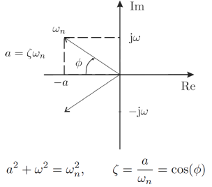
Damped oscillator
For a damped system d > 0, the frequency of the oscillations will be smaller than the natural frequency of the undamped system.
For a marine craft a reduction of 0.5% in the natural frequency is common.
The term under the square root is equal to the relative damping ratio. Undamped oscillator: a = 0
Heave, roll and pitch damping
To determine the linear damping in heave, roll and pitch, we use the following formula for linear damping:
where r is the design parameter.
Surge, sway and yaw damping
To determine the damping in these states we need to treat each of them as a pure mass-damper system. Linear damping for such a system can be found by specifying the time constant T > 0 corresponding to:
which for the design parameter T = m/d is equivalent to
This yields the following design formula for linear damping
(For marine craft we can specify the time constant).
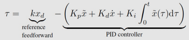
SISO linear PID control
PD control law applied to a mass damper spring system: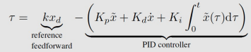
Closed loop system:
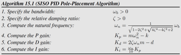
PID pole-placement formulas:
(integral time should be 10 times slower than the natural frequency)
Relationship between natural frequency and control bandwidth
For a critically damped system with relative damping ratio = 1, this expression reduces to:
Control bandwidth gives us information about how fast of a reference we can follow.
Main result (PID controller tuning rule)