MEMS
MEMS is the technology of microscopic devices, particularly those with moving parts. They usually consist of a central unit that processes data and several components that interact with the surroundings.
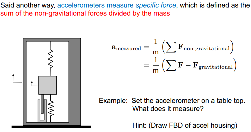
MEMS accelerometer
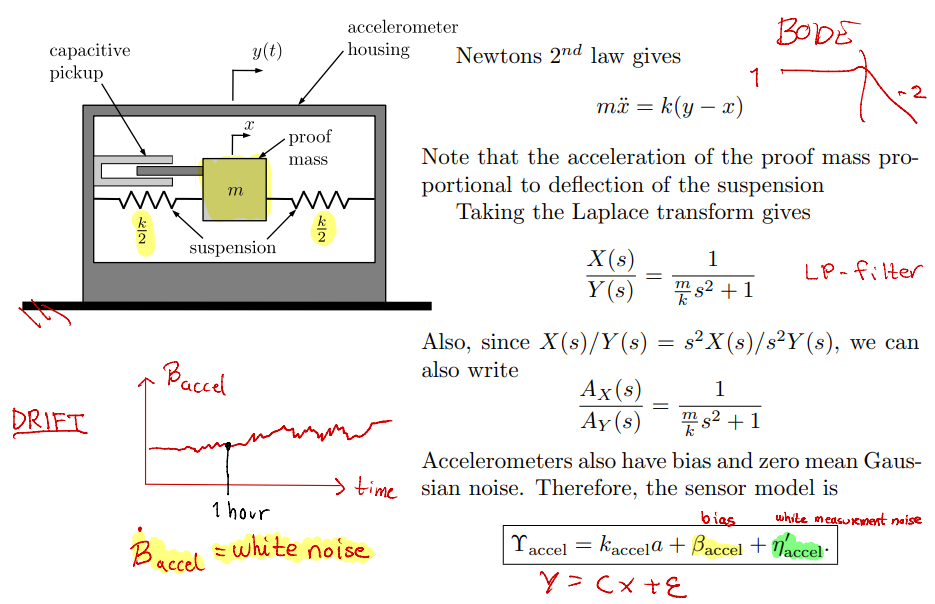
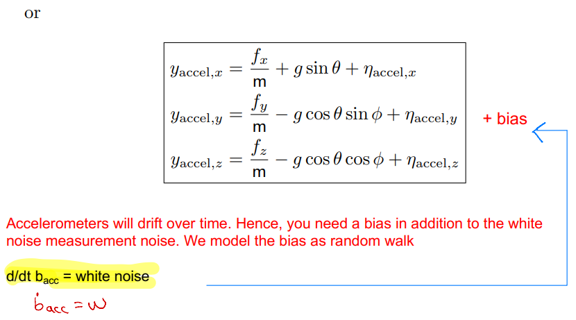
Acceleration measurement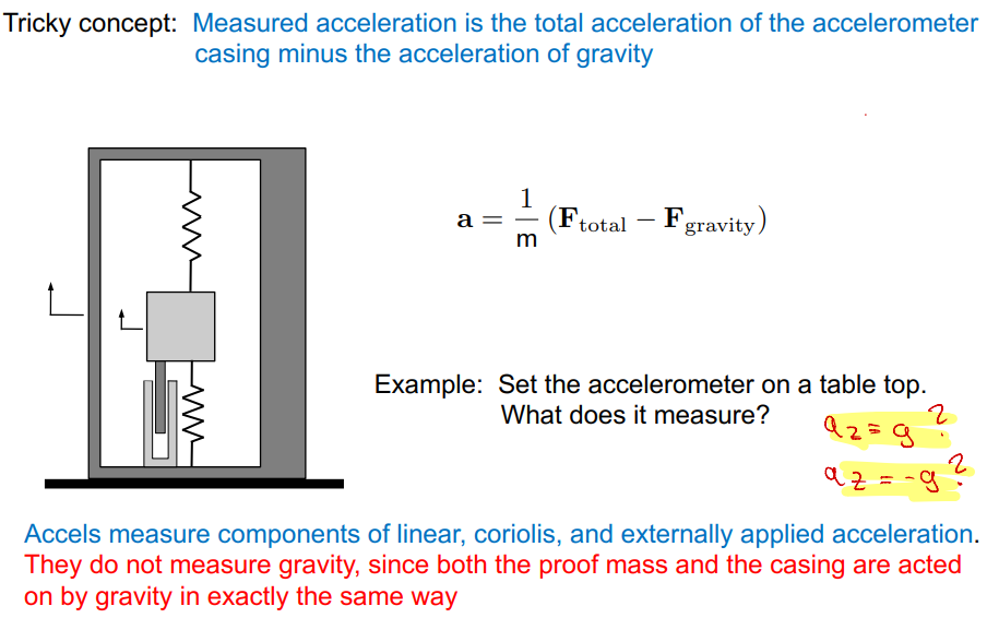
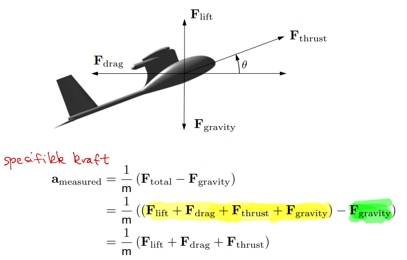
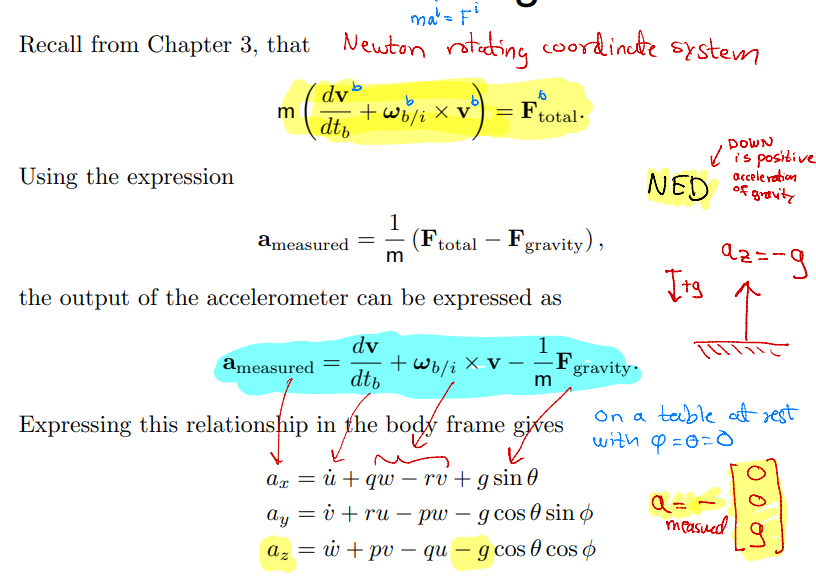
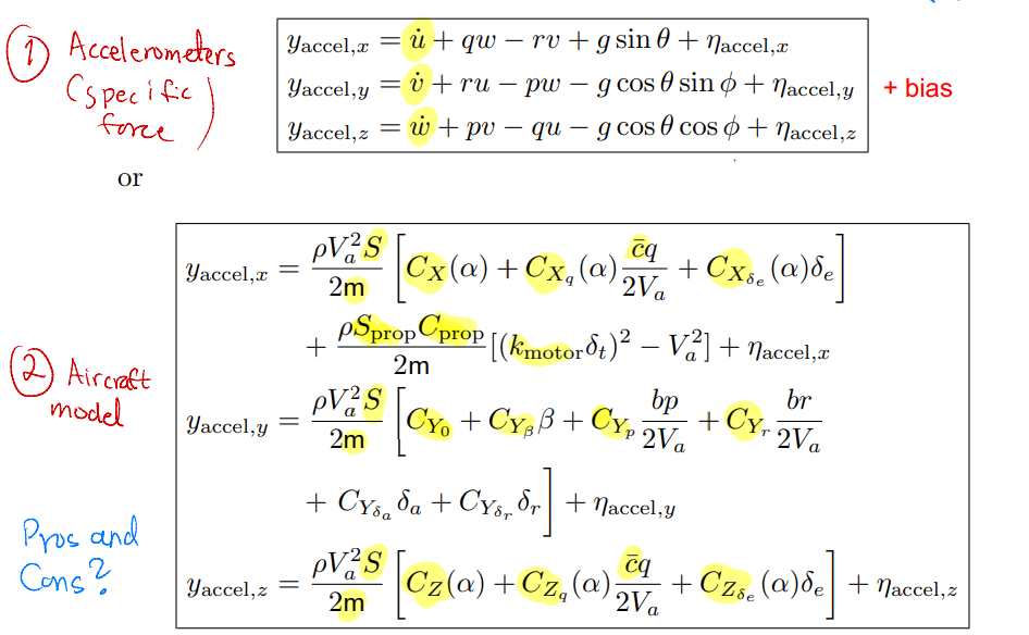
Accelerometer models
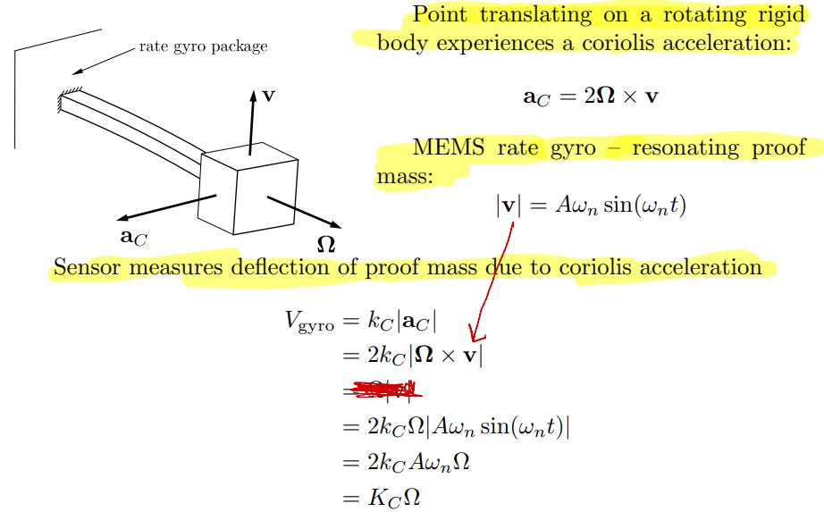
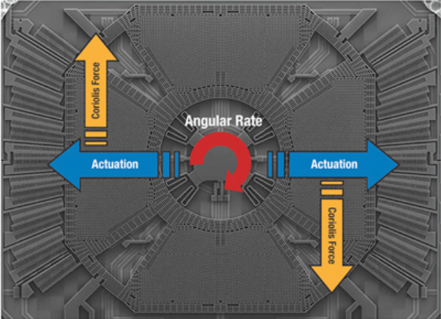
MEMS rate gyro
It is more correct to use attitude rate sensor (ARS) for MEMS. It it not a gyro.
ARS figure
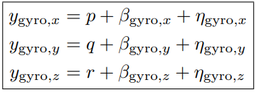
ARS model
The manufacturing process implies that rate gyros will have a drift term, as well as zero mean Gaussian noise:
where is bias and is white measurement noise.
is in units of voltage. Calibrating to units of rad/s gives:
ARS will drift over time. We model the bias as random walk:
Pressure measurement
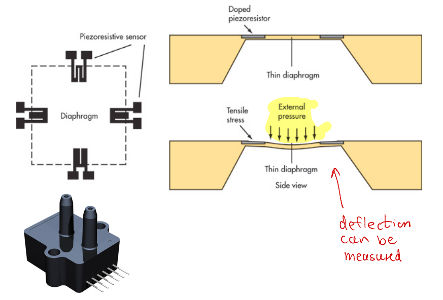
Altitude measurement
The basic equation of hydrostatics is:
is constant.
Using the ground as reference, and assuming constant air density gives us:
AGL = above ground level.
Below 11.000 m we can use the barometric formula:
where = standard pressure at sea level = standard temperature at sea level = rate of temperature decrease = gravitational constant = universal gas constant for air = standard molar mass of atmospheric air
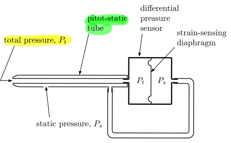
Airspeed measurement
From Bernoullis equation:
or
Pitot-static pressure sensor measures dynamic pressure:
Magnetometers and digital compasses
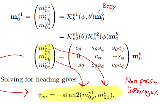
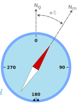
Heading is the sum of declination angle and magnetic heading
Magnetic heading determined from measurement of body-frame components of magnetic field projected onto horizontal plane
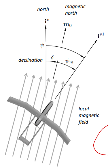
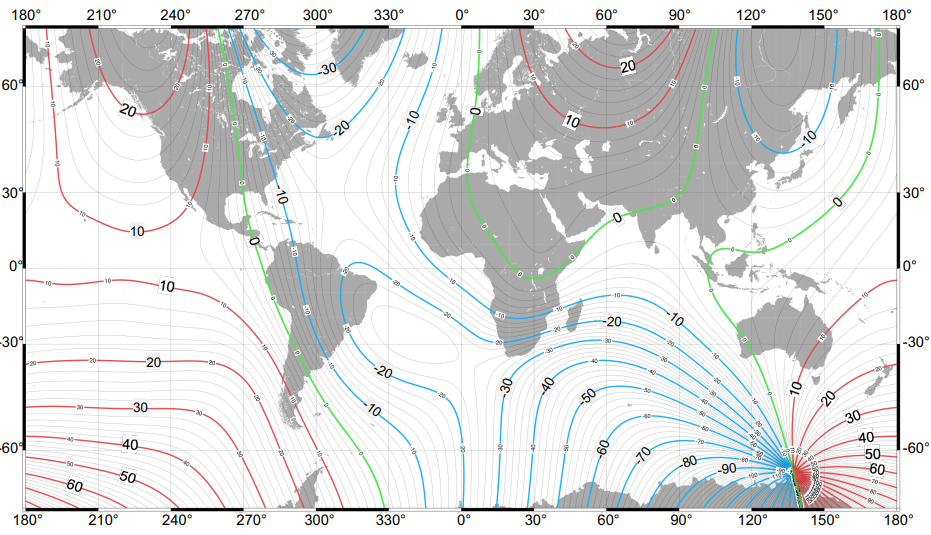
Magnetic declination
Magnetic declination or variation is the angle on the horizontal plane between magnetic North (the direction the North end of a compass needle points, corresponding to the direction of the Earth’s magnetic field lines) and true North (the direction along a meridian towards the geographic North Pole).
Magnetic North is moving!
Magnetic declination variation
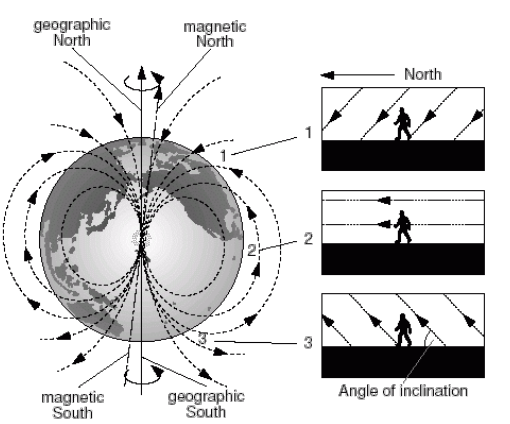
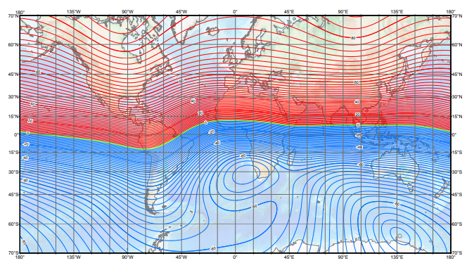
Magnetic inclination
Magnetic dip, dip angle, or magnetic inclination is the angle made with the horizontal by the Earth’s magnetic field lines. This angle varies at different points on the Earth’s surface.
Global positioning system
GPS error sources
- Time of flight of radio signal from satellite to receiver used to calculate pseudorange
- Called pseudorange to distinguish it from true range
- Numerous sources of error in time of flight measurement:
- Ephemeris Data
- errors in satellite location
- Satellite Clock
- due to clock drift
- Ionosphere
- upper atmosphere, free electrons slow transmission of GPS signal
- Troposphere
- lower atmosphere, weather (temperature and density) affect speed of light, GPS signal transmission
- Multipath Reception
- signals not following direct path
- Receiver Measurement
- limitations in accuracy of receiver timing
- Small timing errors can result in large position errors
- 10 ns timing error à 3 m pseudorange error
GPS error characterization
Cumulative effect of GPS pseudorange errors is described by user equivaltent range error (UERE). UERE has two components:
- Bias
- Random
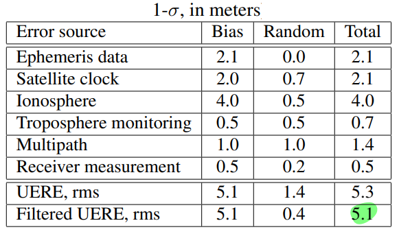
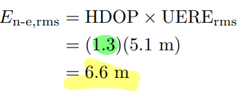
Effect of satellite geometry on position calculation is expressed by dilution of precision (DOP). Satellites close together → high DOP DOP varies with time Horizontal DOP is smaller than vertical DOP Nominal HDOP = 1.3 Nominal VDOP = 1.8
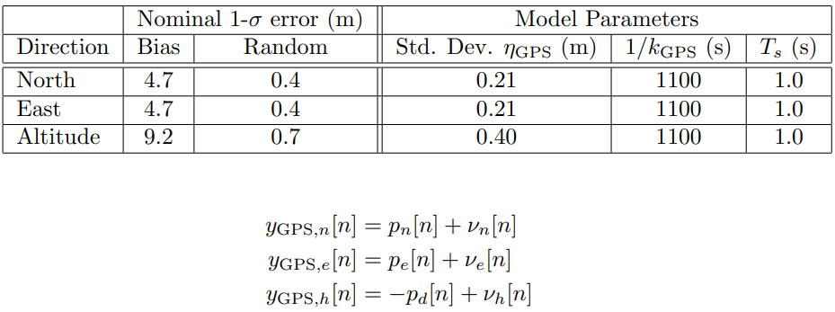
Total GPS error (RMS)
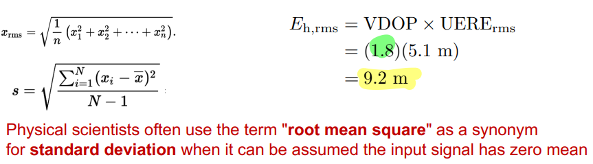
Standard deviation of RMS error in the north-east plane:
Standard deviation of RMS altitude error:
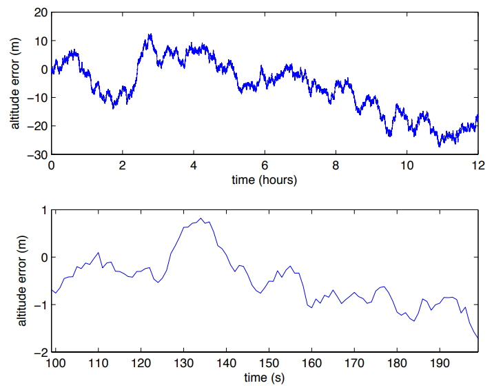
GPS error model
Interested in transient behavior of errors - how does GPS error change with time
We use Gauss-Markov error model proposed by Rankin