Successive loop closure
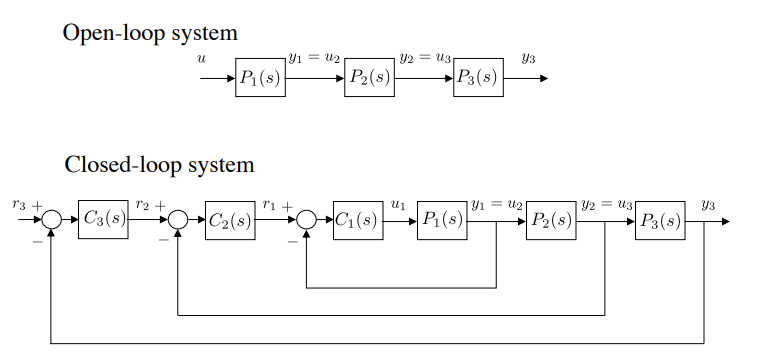
The inner loop is a unit- loop up to the bandwidth . The middle loop is a unit- loop up to the bandwidth .
The bandwidth of the inner loop should be 5-10 times faster than the outer loop.
Saturation limits
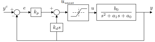 The control signal is largest immediately after a step on , at which point the output of the differentiator is essentially zeros. Therefore . Let be the input saturation limit, and , the largest expected step, then set
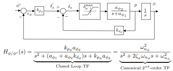
The closed loop transfer function is:
Equation terms gives
Lateral-directional autopilot
DOF 2,4,6 is called lateral dynamics.
Roll rate , integrate to find roll angle. We neglect q and r. So the roll equation gets integrated twice to end up with the roll angle.
The inner loop should be approximately 1. So the commanded roll angle should be almost the same as the roll angle calculated in the inner loop.
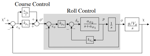
Roll autopilot
Design parameters are and .
Gains are given by:
A good suggestion is to not have any integrators inside the inner loops, including the roll loop.
- Integrators add delay and instability, not optimal for inner loops.
- An integrator will be used on the course loop to correct for steady-state errors.
By removing the integrator in the inner loop, we might get a stationary error, but this will be fixed by the outer loops integrator.
Course hold autopilot
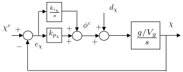 For the course loop, note the presence of the input disturbance. Using a PI controller for course, the response to the course command and disturbance is given by:
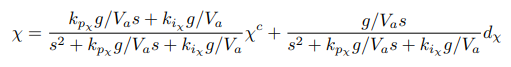
Note:
- There is a zero in the response to the course command c.
- The presence of the zero at the origin ensures rejection of low frequency disturbances.
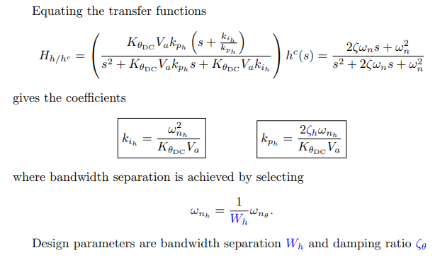
Equation coefficients to canonical TF gives:
or
Design parameters are bandwidth separation and damping ratio .
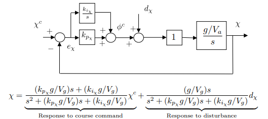
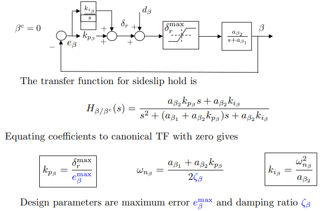
Sideslip hold autopilot
It is necessary to have a autopilot that regulates sideslip to 0.
Summary
If model is known the design parameters are:
Inner loop (roll attitude hold)
- - Error in roll when aileron just saturates.
- - Damping ratio for roll attitude loop.
Outer loop (course hold)
- - Bandwidth separation between roll and course loops.
- - Damping ratio for course hold loop.
Sideslip hold (if rudder is available)
- - Error in sideslip when rudder just saturates.
- - Damping ratio for sideslip loop
Longitudinal- directional autopilot
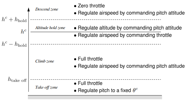
Longitudinal flight regimes
Longitudinal transfer function - Pitch
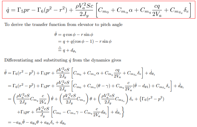
The differential equation model is
with associated transfer function:
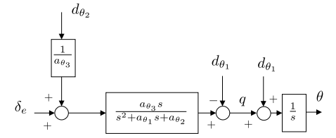
Deriving the transfer function from elevator to pitch angle
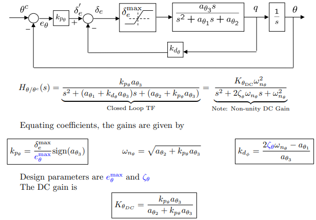
Pitch attitude hold autopilot
Altitude hold using commanded pitch
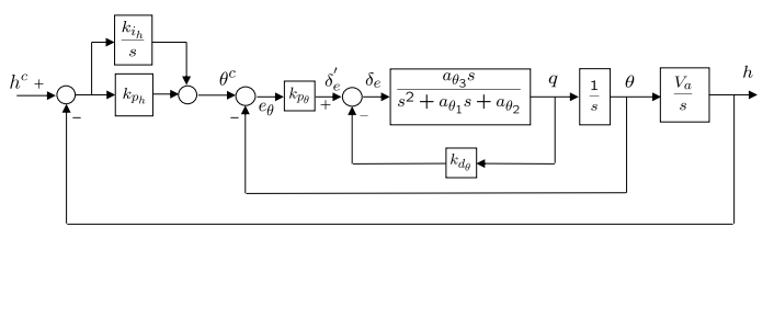
Provided pitch loop functions as intended, we can simplify the inner-loop dynamics to .
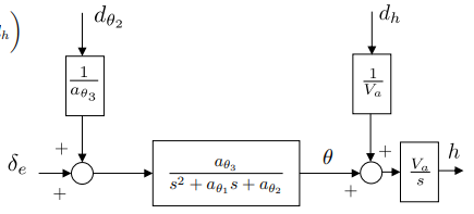
Longitudinal transfer function - Altitude from pitch
To derive a transfer function from pitch to altitude (assuming constant air speed):
where
The associated transfer function is:
Altitude from pitch simplified
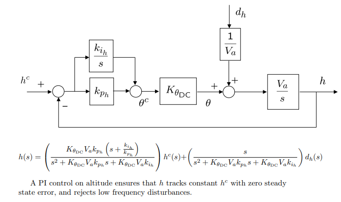
Altitude from pitch gain calculations
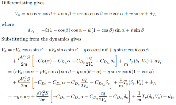
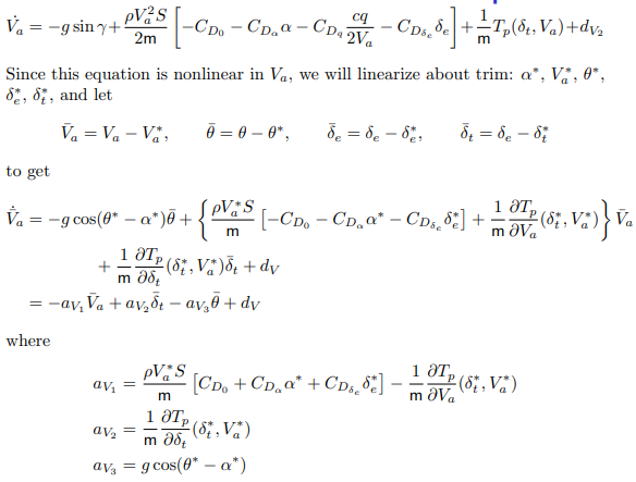
Longitudinal transfer function - airspeed
Both pitch angle and throttle strongly affect airspeed. We wish to derive this relationship.
If there is no wind, then:
 ‘
‘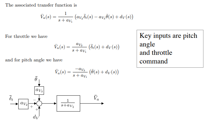
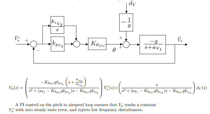
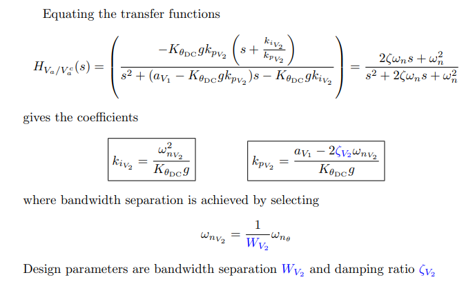
Airspeed hold autopilot using commanded pitch
Airspeed from pitch gain calculations
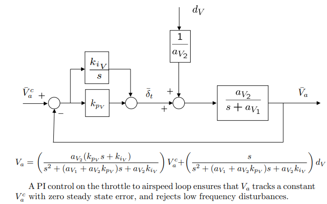
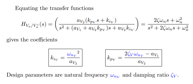
Airspeed hold autopilot using throttle
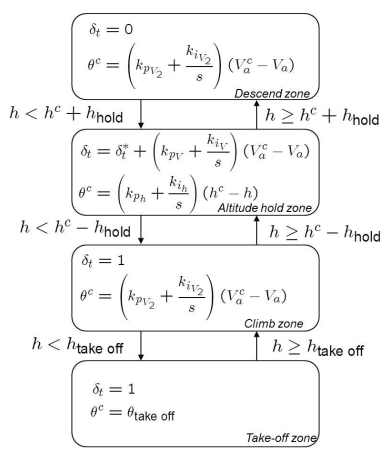
Altitude control state machine
Summary
If model is known, the design parameters are
Inner loop (pitch attitude hold)
- - Error in pitch when elevator just saturates.
- - Damping ratio for pitch attitude loop.
Altitude hold outer loop
- - Bandwidth separation between pitch and altitude loops.
- - Damping ratio for altitude hold loop.
Airspeed hold outer loop
- - Bandwidth separation between pitch and airspeed loops.
- - Damping ratio for airspeed hold loop.
Throttle hold (inner loop)
- - Natural frequency for throttle loop.
- - Damping ratio for throttle loop.